Wednesday, July 13, 2022

Slow going

This project has been a slow burner.  Mostly because I'm eating in the FAA to get my registration transferred.  But I'm using that as an excuse to take my time.

I have made some progress though.  The motor is mounted and I've started building battery packs.

Tuesday, March 8, 2022

Motor Update

I received the motor it's a FreeRCHobby 240105

The Rotax 447 was pulled

An empty engine compartment

The electric motor is trial fit

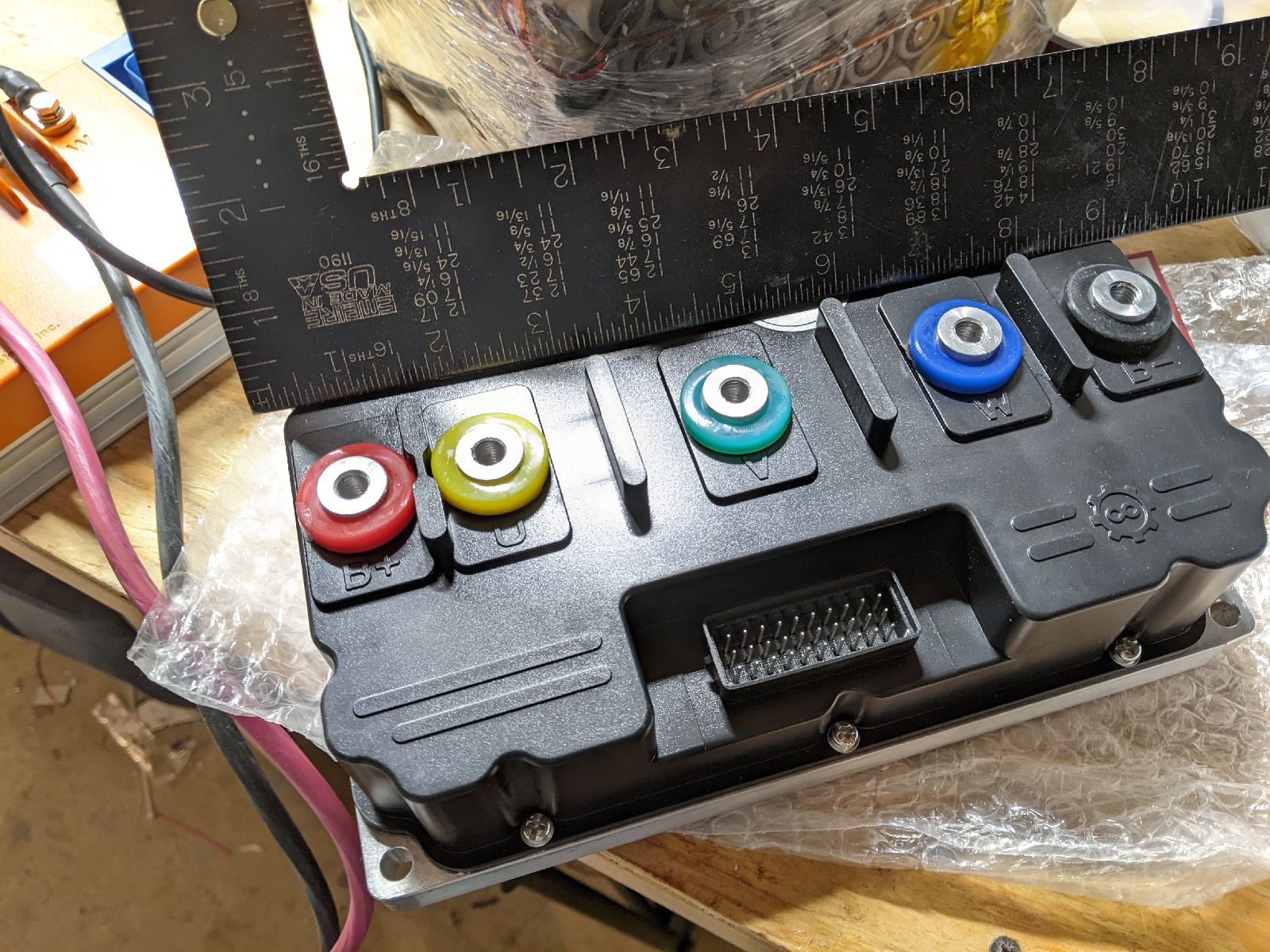
The motor controller and motor

I started work on the engine mount and prop adapter.


Tuesday, January 25, 2022

It spins

 I wired the throttle, display, and enable to the test controller.  After about an hour of setting parameters in the "bacdoor" app (controller configuration software) I was able to get it to start to spin.  There's more fine tuning to do, but I have movement!

Tuesday, January 18, 2022

Thursday, January 13, 2022

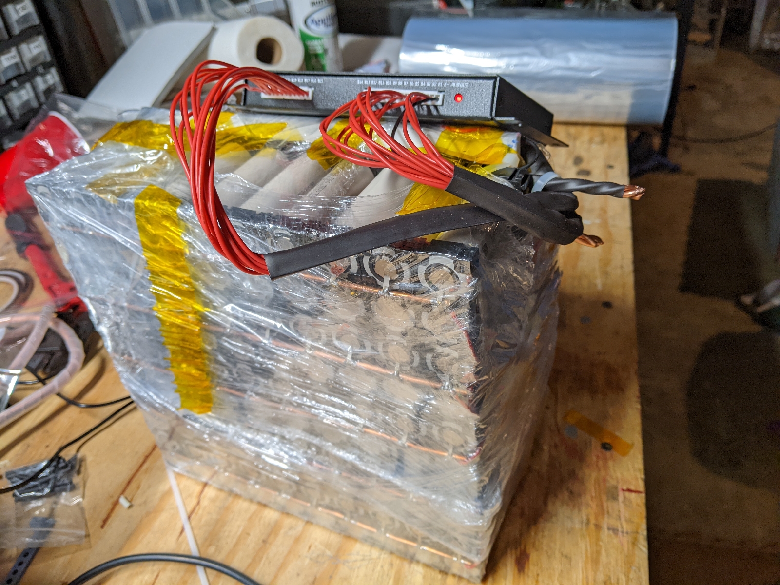
First battery build... lessons learned

Here are some things I'd do differently on the next pack
  1. The pack needs structure, the wrap is good, but not enough to really give it strength.  It needs something to hold it together.  I really like the plastic cell spacers... yeah the pack is bigger but much stiffer
  2. I don't think the pack will stand up well to flight vibrations in a few areas, mostly has to do with the fuse being so small and while they are strong, they can't handle pack loads and vibration.  Where the packs join, it's a real weak spot. Each sub-pack needs a strong less stressed bus bar... I shouldn't have joined them just using fused links.
  3. For the parallel bus bars, I want to use nickel strips next time, not copper, less soldering is better.  Welding is much stronger, faster, and simpler.
  4. Thicker shrink wrapping
Building larger packs than 200 cells is going to be very cumbersome (and heavy to handle).  I need to re-think some of the logistics of assembling the batteries going into the wings.  They are 480 cells spread out over a meter long on the entire wing, and likely be a bit over 35kg (77lbs).

My plans to build the wing battery as actually 20 serial sub-packs of 24 parallel batteries which can be assembled as they go into the wing are unchanged.  Each sub-pack would (3x8) half-width.  I just think it will need to be wired as it goes into the wing or it needs a way to be inserted smoothly.

Wednesday, January 12, 2022

All wrapped up!

Okay here it is. All the cells are fused and bussed, all the balancing leads are soldered and stain releived,  the connections were good and the battery balancer is running!

decasing and balancing

To remove all of the rap. Now I'm balancing the one battery which I charged.

encased battery

I forgot to install the balance leads before I in case the battery. But here it is in case it'll all have to unwrapped and rewrapped.

Tuesday, January 11, 2022

Making sparks

I started spot welding the batteries. I'm using nickel-plated steel soldered to copper bus bars. I definitely like the square plastic pattern much more than the hexagonal RTV bonded cells. The plastic squares are just much more solid.  The plastic also gives some nice standoff for the bus bar to protect the cells from solder heat.  I used wooden sticks on the hexagonal to achieve the same. 
Finally, welding is very participants about the metals.  Aluminum and copper don't weld with settings on my spot welder.  Too low and nothing bonds, too high and it just obliterates the nickel strips.  I know they can weld, just need to find out how.

Sunday, January 9, 2022

More battery building

I assembled another pack of 100 from the snap together blocks of 1x3 and 1x2. I'd like to try both to see which one is better and if it really makes a difference. Clearly the size difference isn't important.

Wednesday, January 5, 2022

Assembling the test pack

I started assembling the batteries today this is just the first few rows.


I 3d printed a cell holder which I use to hold the high temp rtv till it dries.

Here is the bms and wiring harness.

Thursday, December 30, 2021

What 20kwh looks like

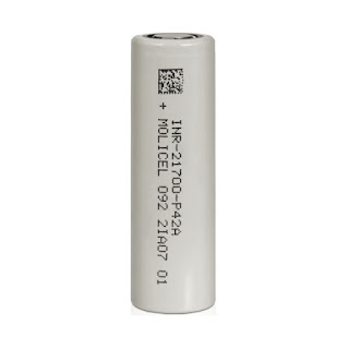
Ok, so this is actually more like 18kwh, but you get the idea.  I received the last batch of boxes of 200 cells, one is already open. I tested one random cell, it has a staggeringly low impedance 35ohms.  These are legit cells and they should work very well!  If you compare that to a typical "good" 17650 cell, they are 200ohms.  That means these batteries will generate less heat under load.  That's a great thing!
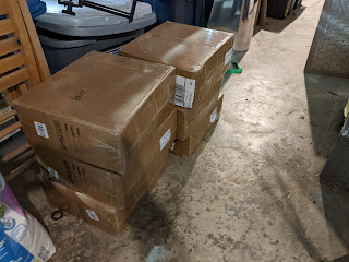
Just sitting like they are, these weigh just under 25lbs for each box of 200 cells, without wiring, balancers, etc.  So that's 150lbs right there.

Thursday, December 23, 2021

Upgrades

Motor Controller Upgrade

The motor controller I had selected was not appropriate.  It had the right voltage and current, but the continuous power rating would have been an issue for it.  Working with the supplier I bumped up the controller to a larger model which has a higher current rating and a much higher sustained power rating 18kw.


Motor Upgrade

I worked with the engine manufacturer to have them do the custom engineering work to coaxially mount the two 238100 motors I purchased.  I was planning to do this myself, but it was very reasonable to have them do that work and it's one less thing I will need to figure out.


Friday, December 17, 2021

Updates: Motors, Batteries & Controller purchases

All major components are purchased!

I now have on order both motors, the last controller, the last set of batteries...

Motors 

Two brushless 238x100mm motors of 50kw peak (30kw continuous) power have been purchased!

Motor Controller

I purchased a 120V 600A peak 200A continuous 3-phase programmable motor controller.   My other controller is a 72v 440A peak 200A continuous.  I wanted two different controllers on purpose to have different failure loads and modes.

Batteries

The first batch of 600 cells looked very good.  So I purchased the second half, 800 more.  For practice, I'm building a 6S40P 17680 assorted laptop battery pack for my off-grid hangar solar system.  I want something big, not huge, and most importantly, not flying to get some learnings on.


Tuesday, December 14, 2021

Keep your cool... but not too cold!

The Molicel cells chosen stated operating range is  -40°C to 60°C.  That's a pretty good range, but really operate best and are "happiest", make full cycle lives and operation to spec when they are around the same temperature us humans like 22°C.  Here are some typical operating temperatures

Unvented Hangar: -10°C - 60°C
Flight(pilot limited): 10°C - 50°C
Sitting outside: -20°C - 50°C

Typical operating range: 10°C - 30°C

So while the operating range is workable, it's not "that" far from the absolute limits.  And those limits are hard limits.  The battery pack will definitely be temperature sensitive and requires active temperature control, especially cooling under high loads in flight.  The simplest/lightest active cooling system is air-cooled.   The nose batteries should receive good airflow from the existing motor cooling inlets.  I am less concerned about them.  The wing-mounted batteries will be sitting inside styrofoam in a cavity carved from the leading edge of the wing.  They will be well insulated (which is a very good thing), but unless some accommodations are made, they would not receive any airflow in flight.  To remedy this, the layout of the pack will accommodate channels where outside air from a NAC duct under thewing can flow through the battery packs in flight to cool them.


Air will flow in three channels formed by the batteries themselves and a baffle.  There's an outside channel between the outside batteries and the walls of the foam cavity, between the first and second rows of batteries, and an inner channel formed by the baffling which will slide into a hot-knife-cut-notch in the foam cavity.

To help determine appropriate cooling and operating parameters several temperature sensors (up to 15) will be installed in the battery packs and monitored during test flights to determine the best-operating conditions and limits.  Those limits will inform normal operating limits.

The temperature sensor is a DS18B20.  These are uniquely identifiable solid-state digital sensors.  They operate from -55 to 125°C and ±0.5°C Accuracy from -10°C to +85°C, so pretty perfect for these operations.  They use a "1-wire" bus-style protocol, so they can all be "ganged" together sharing a single communication wire to a microcontroller that can collect and display the information to the pilot.  That will likely be its own future post.


They can be purchased with some environmental and water resistance.  One potentially layout could be...

Each Motor - 2
Each Controller - 2
Each forward battery - 2
4 per wing battery - 8
Outside Air Temp - 1

Total count 15


High currents and Copper vs. Aluminum

For this post, I'm going to concentrate on just the in-wing battery packs.  They are by far the largest packs with the heaviest load.  The wings hold 74% of the batteries, which means they need to supply 74% of the current for all possible modes of operation.  Due to the nature of the twin design, there are several loads to consider. All loads are per pack

Normal Cruise - 57A

Normal TakeOff - 180A

Single-Engine Climb - 310A (74% of controller maximum 420A)

So worst case we need 310A supplied from one battery for up to 2 minutes.  The runs from the battery to the controller are somewhere around 2m.  Each battery needs its own run of pos & neg, so 8m of wire is capable of providing 310A over 4m (total run length).  Wire gauge charts recommend 2/0 ("00") as the appropriate AWG for this load. That's about 30lbs of copper!  That's a _LOT_ of copper.  But for large loads, there is an alternative... Aluminum.  Aluminum has a higher resistance, so we'll need a bigger wire, but it's 5x lighter than copper.  So the same run in 4/0 ("0000") is 4 lbs.

What's the catch?!  Aluminum as a conductor is not all good news.  There are three (maybe two) areas of concern, Aluminum, relative to copper, is brittle. It must be well secured through the entire run (especially the connectors) and as vibration-free as possible or the wire will snap.  Second, aluminum suffers from oxidation effects which lead to poor connection and potentially fire, so all connectors must be cleaned, coated with a "noalox" corrosion inhibitor compound.  And finally, all of the aluminum wiring and connections will need a regular inspection for the above reasons, where copper would have been installed and forget it.

Monday, December 13, 2021

Battery Configuration

I've considered many configurations, I have started doing the final battery layout.  1400 cells total configured in four-packs total.


Front Battery Set: These are two 20S9P 2.7 kWh packs stacked vertically.  I color-coded the cells in the same parallel string the same (red, purple, blue, green, white).  This battery pack does a serpentine up, down, zig-zag from left to right flipping and s +/- up every other string.  A smaller copper bus bar will be used here on the flips to keep the batteries in the parallels balanced.


The wing battery pack is long and thin, it's designed to fit in the wing leading edge.  It's configured 20S26P, 7.9 kWh each (one in each wing).  The leading edge will be hollowed out to accept this pack from the root prior to assembling the wing.

On this wing battery pack, they are configured in parallel groupings of 2x13.  I'm using aluminum bus bars running down the middle of the set of two cells.  Connecting the battery to the bus is 24GA (10Amp) fusing wire spot welded from the battery ends to the bus bar.

First Pack Assembly

I unboxed the batteries for the first pack. 20s9p, 180 cells.  This represents 2.7 kWh of capacity.  Only 1220 cells left and 17.3 kWh.

Wednesday, December 8, 2021

Battery Analysis

Electric vehicles are really 90% about batteries, everything else is just what it takes to move them, hold them, heat them, cool them, charge them and draw current from them without catching fire.


I have a spreadsheet that I developed over the years to help me decide which battery to purchase and how to arrange them to achieve my mission.  The spreadsheet takes as input the mission profile.  It has the motor power and volts, it also requires you to input three phases of flight, TakeOff, Climb and Cruise (descent and landings are ignored in this simplified model).  

Then I scoured the internet looking for battery options, there are so many types with different discharge rates, weights, configurations, etc.  So I created a sheet where you provide all the basic specifications for a cell or battery and it would attempt to multiply it in series and parallel to match the mission requirements.

From this, the analysis I was able to determine the most appropriate battery for my application.  I can tweak the mission to make the battery configuration match.

So Why?!

Why?

So this is a very unusual project... and it's probably important to take a step back and answer the most basic questions... Why?  You're spending all this money to make an airplane that's heavier, and won't fly as far?

Why the Silhouette?


For all the reasons I'll get to shorting, I wanted my next big aviation project to be an electric aircraft.  There are a few boxes which have to get checked.  First, it must be experimental certificated (preferably homebuilt) for ease of conversion/regulation.  The second it needed to be very efficient.  Those to criteria really drop the list considerably.  Candidate aircraft are;


The Task Silhouette is a very unusual aircraft.   It's the only single place motorglider on that list.  That is a very big deal, it's a lot easier to convert a single place than a two.  Very few were ever built, only a very few are still airworthy and flying.   It's performance is good, but not exceptional.  24:1 with the wingtip extensions is good.

The reason so few where built was because they never had a good powerplant.  I think if they had had an electric option for this airframe, it may have faired quite a bit better in build numbers.

Cost

I personally believe that the expense in time and money are some of the biggest factors in keeping light aviation from becoming more attainable.  There are many costs in aviation, but the biggest single cost is fuel.  It's typically 90% of the operating costs and for my RV-4, which I fly 100hrs/yr, it's 60% of the total cost.  Electric aircraft can't fulfill most missions in aviation today, but they can do some and at a massively reduced operating cost.  I'll go into more detail in a moment, but as an example, the Electric Silhouette would cost $1 per flight hour.  Compare that to $15 for the 2-cycle gas-oil version and $31 for my RV-4.   In actuality, I intend to charge it with the off-grid hangar solar panel system I've already installed, so in actuality, it won't cost anything to fly. 

Simplicity

I have a passion for simple, efficient engineering.  I want an aircraft I can walk around, hop in, flip a switch and go.  That brutal simplicity intoxicates me.

Safety

Twin electric motors have exactly two moving parts, relatively low operating temperatures, and nothing trying to be ignited (hopefully).  This setup works very well for the Silhouette airframe.  The Rotax 447 has ver moving parts, but they are under extreme thermal and mechanical stress.  Failures are not uncommon and that's not acceptable.  The lack of suitable engine choices was one significant reason the Task Silhouette never gained three-digit build numbers.  It is a very small aircraft and that is a major factor as well.

Mission

So this is where it gets personal.  I'm building this for MY mission, and honestly, it's pretty simple.  99% of my flying has two profiles.  

Profile 1

I love to jump in a plane near the end of the day and just put the troubles of the day underneath me... To twist Jimmy Buffet; Changes in Altitude changes in Attitude!  These flights are always short, 20-30 minutes max. 

Profile 2

I'm blessed that I have an opportunity most good weather Saturdays and or Sundays to fly 45nm to my glider airport where I can soar, tow, and or instruct all day, then I fly home.  This is a pretty straightforward mission, fly 90nm round trip in a day, with a 4-6hr recharge opportunity in the middle.

I would argue there's a third profile, enabled by the right kind of aircraft which is not too dissimilar from profile 1, but I'll name it.

Bonus Profile 3

Get in the motorglider after work on the best days and find a few late-afternoon thermals or a cloud street and see how far I can get, hone my thermal skills, then motor home.

So those are my missions, and I need to choose my electric system to match all those missions.  I chose this specific mission profile.

2 Minutes at 100% full power, take-off

10 minutes at 66% climb power

90 minutes at 15% "best economy" OR 60 minutes at 25% "good speed cruise"

That mission meets all of those objectives.  I've also found that in electric vehicles (my experience is with cars) error on the side of having too much battery, it can't hurt and it makes everything simpler.

Slow going

This project has been a slow burner.  Mostly because I'm eating in the FAA to get my registration transferred.  But I'm ...